In the field of industrial automation, integrating a rugged mini pc with CAN and Modbus networks enables seamless communication across devices. More than 65% of manufacturing plants rely on the CANopen protocol, while nearly 55% use Modbus TCP/RTU for monitoring and data acquisition. Our Mini PC series features various hardware interfaces, including CAN transceivers, RS-485 ports, and optional PCIe expansion. Next, we will examine the software stack, which includes open-source CAN drivers, SocketCAN, and Modbus libraries. Then, we will configure device addressing, baud rate, and network topology. Next, we will introduce protocol bridging, data mapping, and error handling strategies. Finally, we will test to ensure that there are no problems.
Rugged Mini PC Hardware Interface for CAN Bus Connection
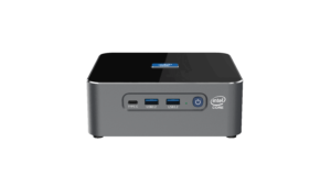
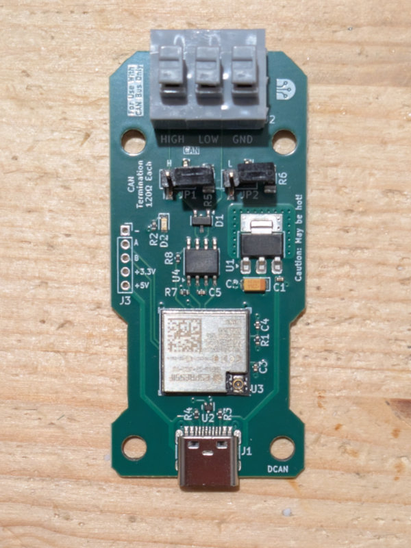
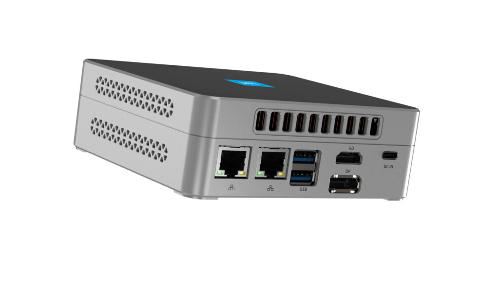
To connect a rugged mini pc to a CAN network, a reliable physical layer interface is required. Most industrial mini PCs come with one or two onboard CAN 2.0B ports, equipped with differential transceivers and galvanic isolation to prevent ground loops in noisy environments. For example, some mini PCs include two screw-terminal CAN ports, rated for 5V and 12V networks. Additionally, if your application requires a multi-bus topology or CAN FD support, PCIe-to-CAN expansion cards provide up to four additional channels.
At the same time, we install 120 Ω termination resistors on both ends of the CAN network to prevent signal reflections and ensure reliable communication up to 1 Mbps. Engineers can reconfigure the RS-232/485 port using an external CAN gateway to enhance system flexibility. By choosing the right interface, you can ensure robust, noise-resistant communication between the Rugged Mini PC and CAN-based sensors, actuators, and controllers.
Software Stack and Driver Configuration
With the physical link in place, the next step is to install a real-time Linux kernel with SocketCAN support. Thus, we can get the native CAN interface to handle candump through standard Linux network tools. I enabled the can0 and can1 interfaces in /etc/network/interfaces, specifying the baud rate to 500 kbps or 1 Mbps to match your CANopen device. For Modbus integration, I deployed libmodbus for RTU over RS-485 or Modbus-TCP server daemon and configured port 502 in the firewall. Additionally, Node-RED or Python scripts utilizing python-can and libraries enable the quick prototyping of data acquisition and control flows. By layering these open-source stacks on your Rugged Mini PCs with pymodbus, you can create a versatile platform that communicates with both CAN and Modbus nodes simultaneously, enabling a unified data flow.
Protocol Configuration and Data Mapping for Rugged Mini PC
Configuring protocol parameters on the Rugged Mini PC involves assigning unique node IDs to each device and mapping these IDs to registers or CAN object dictionary entries. For example, CANopen node IDs (1 to 127) are assigned, and SDO/PDO communication parameters are set through EDS files to avoid address conflicts and ensure timely data exchange. The canopenPython package is used to upload device configurations to each node and monitor heartbeat messages in real time. In Modbus RTU, slave IDs (1 to 247) are set, and holding and input registers are defined that are consistent with the PLC register mapping to standardize data access.
Network administrators establish Modbus TCP port 502 in the firewall and map the TCP unit ID to the RTU master via transparent gateway services. This enables precise data mapping on the Rugged Mini PC, ensuring the accurate association of CAN signals and Modbus registers.
Bridging CAN and Modbus Networks
In mixed-protocol environments, the Rugged Mini PC often acts as a protocol bridge, seamlessly converting messages between CAN and Modbus protocols. In addition to the native CANopen master, I also run Node-RED flows that subscribe to SocketCAN topics and republish values through Modbus TCP registers, enabling the SCADA system to read and write CAN sensor data without native CAN support. I deployed an OPC UA server on the Rugged Mini PC to expose CAN and Modbus variables through a unified, platform-agnostic interface.
Additionally, mapping tools can dynamically handle real-time data scaling, unit conversions, and error code translations. By bridging protocols at the edge, the Mini PC can reduce PLC logic complexity, centralize network management, and speed up deployment.
Error Handling and Network Diagnostics
Maintaining reliable CAN and Modbus communications on the rugged mini PC requires powerful diagnostic and error-handling capabilities. The SocketCAN candump utility actively logs receive errors, bus-off events, and message overflows to the system log. Therefore, I set up automatic alerts when the bus error counter exceeds a predefined threshold. The modpoll script actively polls Modbus slaves at set intervals, logs CRC errors and timeout events, and activates SMS/email alerts via the alarm server. The hardware watchdog timer on the rugged mini-computer automatically restarts the hung interface and restores the connection, eliminating the need for manual intervention. This thereby maximizes the overall system uptime and reliability.
Seamless integration of CAN and Modbus
Integrating the Rugged Mini PC with CAN and Modbus networks involves selecting the appropriate hardware interface, configuring open-source software stacks, accurately mapping protocols, bridging data streams, and implementing diagnostic and security best practices. To achieve this, we configured physical CAN transceivers, enabled SocketCAN and libmodbus, mapped node IDs, deployed bridge daemons, and protected the system with VLANs and hardened operating system configurations. We then monitored and maintained the network to ensure continued operation and unify various industrial protocols.